Markings and Codes
Some ceramic disks wear a color "skull cap" to indicate the dielectric. These will also use a XXM format to indicate value (where the M is the multiplier), and a tolerance letter from Table 5 above.
For example, 102J with a black cap would a 1000 pF 5% C0G. There is a similar system for Class 2 and 3 ceramics.
More of these are at http://www.fust-electronica.nl . All this is little problem for equipment manufacturers who know what they are buying. The hobbyist using surplus parts (or someone doing repairs) might at least want to invest in a cheap capacitance meter (or build one).
Also see :
http://www.wikihow.com/Read-a-Capacitor.
http://library.solarbotics.net/pieces/parts_elect_pass_cap_code.html Also has MIL codes
http://en.wikipedia.org/wiki/Ceramic_capacitor
SMD
SMD ceramics will often be marked with a two-digit EIA code (letter plus number) to indicate value. You may also see a one-digit-plus-color-code. See Tables 10 and 11 below. Manufacturers usually offer volume buyers three marking options, EIA standard, custom, and none. None is chosen all too often. Table 10 is an EIA system, but the origin of Table 11 is unknown (I have only seen it used by Philips).
For example, A5 = 1.0 x 105 = 100,000 pF = 0.1 uF, and f9 = 5.0 x 10-1 = 0.5 pF. Simple enough.
The type of dielectric may be indicated with a "bar code" system that uses bars above, below, and on either side of the value code. For example, |XX is X7R with value of XX from table 6 above, and XXI is Z5U. XX is N330 (S2H), XX is N470 (T2H), XX is N750 (U2J). C0G is XX, where the bar is my way of indicating bars >over< the value digits (XX). So for example, |A5 is 0.1 uF X7R. Murata-Erie uses this system, but I don´t know if anyone else does..
SMD tantalums usually have enough room to have the value and voltage spelled out (sometimes without telling you which is which), some use the two-digit EIA code above, and some are marked in other ways. Tantalums can also be found with a voltage code (instead of the tolerance code normally seen on ceramics), as shown in Table 12 below.
So how many ways can you mark a tantalum SMD capacitor? Any number of ways depending on room available and the manufacturer's frame of mind. A 10 uF/25 Volt capacitor might look like:
1
2
3
The above list is not exhaustive. Variations include date codes based on a system of dots, and special voltage/value schemes loosely based on the EIA codes, but with modifications and additions. At least one company sometimes uses the letter part of the EIA code, without the exponent, to indicate uF instead of pF (J would be 2.2 uF).
Military Capacitors
Military capacitors use a long-winded code that gives dielectric, temperature drift, value, tolerance, temperature range, voltage, and failure rate. See http://fcim.csdc.com for that and some other marking codes.
Obsolete Mica Codes
Molded micas (sometimes called "stamp" micas) came in cases with molded-in "pockets" for colored paint dots that identified some combination of value, tolerance, voltage rating, vibration rating, temperature rating, and temperature drift.
Other Obsolete Codes
Someday, may be of interest to people repairing antique electronics. Molded paper capacitors once used a color dot system of the sort used by molded micas.
Additional sites with capacitor marking information.

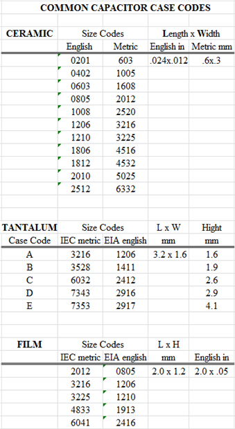
Case size codes are based on the sizes in 0.01s of an inch in English and 0.1 mm in metric.
Example: Case code 0603 (EIA English) and 1608 (IEC metric) is .063 x .031" in English and 1.6 x .8 mm in metric.
The tantalum codes can include higth as well. For example: A 3528-12 is 1.2 mm high and a 3528-21 is 2.1 mm high. Or maybe not. Some companies use "bootleg" case codes instead. So a 3528-21 might be called a B but a 3528-12 might be called a T.
With this system you can define any size code you want and sometimes it seems like people do. Below are only the common sizes for different types of capacitors. In this country the EIA (inch) codes are commonly used for ceramic, but for tantalum and film, the IEC (mm) codes are commonly seen. I include both for no good reason.
First, let's get our nomenclature straight. 1 mF (milli) = 10-3 farad, 1 uF (micro) = 10-6 farad. 1 nF (nano) = 10-9 farad, 1 pF (pico) = 10-12 farad. 1 pF = 10-3 nF =10-6 uF. Nano is rather less common than micro and pico, but it still shows up. "Femto farad " (fF) is used for things like RAM chip storage capacitors, but there are no discrete capacitors in that size range. Well, that's not true. Microwave capacitors go down to at least 50 fF, but are called 0.05 pF.
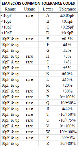
It would be nice if there was more consistency to capacitor markings. If the manufacturer has lots of room (like on big electrolytics) they will usually print everything they can; value, voltage rating, temperature rating, series, even country of manufacture. However, the smaller the part gets, the less information you get until, on the smallest parts there may be nothing at all. On small through-hole ceramics, a two-number-plus-exponent system is often (but not always) used. This, like most marking systems, is based on the picofarad, the lowest common denominator of capacitance. 470 may be 47 (47 x 100) or 470 pF but 471 is almost certainly 470 (47 x 101). 473 will probably be 0.0047. However, 479 will probably mean 4.7 (47 x 10 -1). Values below 10 pF may use "R" for a decimal point, 4R7 = 4.7 pF for example. With luck, you might also find the material (C0G, X7R, etc.) and voltage rating. The tolerance may be next to the value. Table 5 shows the EIA tolerance codes for ceramic capacitors. Once again, don't expect to find all possible combinations of values, dielectrics, and tolerances. The tighter tolerances mostly apply to small C0G capacitors and the looser tolerances to larger Class 2-4 ceramics.
For example, if you see .047K, the value is .047 uF 10%.
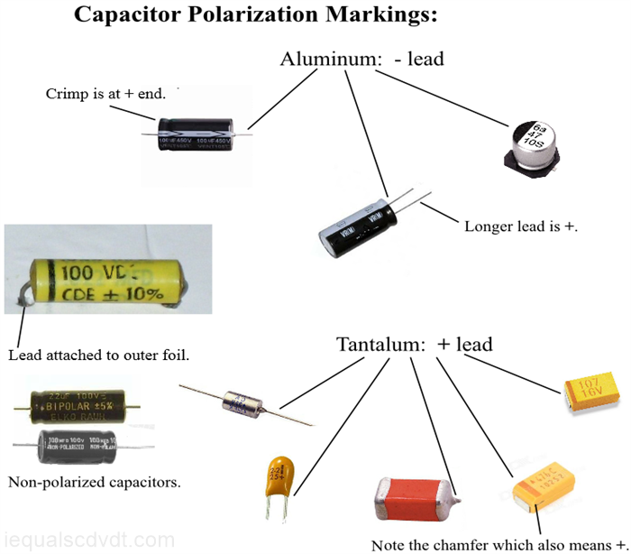
Polarity:
The polarity of electrolytic capacitors is important and manufacturers have a variety of ways of marking the polarity. The aluminum people are obsessed with the negative lead and the tantalum people with the positive lead. There are non-polar aluminum capacitors but I have never seen a non-polar tantalum capacitor. Even film capacitors can have a polarity of a sort. Sometimes a band is used to mark the lead attached to the outside foil. This was universal in the days of hand-soldered AM radios but rare today. This is irrelevant for stacked-foil film capacitors. The picture probably does not cover everything.
value
tolerance
film materials
ceramic types
SMD
case sizes
voltage
polarity
mica
GB/T-2470-1995
With European parts, you may also see capacitors marked with a two-digit system with the "multiplier" letter used as a decimal point. For example, 4700 pF would be written as 4n7, which is 4.7 nanofarads. I understand this is taken from IEC 60062 (which I have not yet seen). Some examples are:
On the right are markings used for tolerance. Tolerance and value are amonge the few markings you consistently see.
China Standard GB/T 2470-1995:
GB/T 2470-1995 (previously called GB 2470-81) is the standard China uses to identify resistors and capacitors. I know little
about it, but I became interested because it is so often used by manufacturers and distributors to identify large motor run, motor
start and lighting capacitors. It is also used for small board-level parts. You often see things like CBB60 or CBB80A-1 (they
sometimes get it wrong on Alibaba and other sites). You may see it but almost never does anyone bother to explain anything
about the system. What does it mean? This is what I was able to find out:
1: C=capacitor
2: B=organic film (polymer film)
D=electrolytic (I think)
3: B= polypropylene
4: A number that gives the type.
60=motor run, equivalent to ANSI/EIA-463, round plastic shell.
61=similar to 60 but in rectangular plastic shell. A uses wire, B uses "quick-connects". Probably for smaller motors.
65=similar to 60 but oil-filled metal can with built in overload protection ("P2 anti-explosion"). Versions are A, A-1, B, B-
1 for different quick-connect configurations.
80=made for use with various lamps, sodium vapor, mercury vapor, others, plastic case. Versions A-1, A-2, B-1, B-2, B-
3, for various connections.
These are a few other codes I have seen, there seems to be many others. This may not be accurate because the Chinese
ecommerce sites often confuse pictures and descriptions:
CD60=motor start, non-polar electrolytic.
CD13=DC storage, welders, UPS, etc, electrolytic
CD263=small electrolytic
CD293=small electrolytic
CBB21=metallized polypropylene, small leaded cap.
CBB22=metallized polyester, boxed
CL20=metallized polyester, axial
CL21=metallized polyester, radial
CL22=metallized polyester, boxed
CH85=microwave oven capacitor, polyester
CH84=polypropylene ?
>>>>> If anyone has more information, send it along. <<<<<
http://webstore.ansi.org/FindStandards.aspx?SearchString=GB%2fT+2470-1995&SearchOption=0&PageNum=0&SearchTermsArray=null%7cGB%2fT+2470-1995%7cnull